Thread machining precision and quality directly impact the overall performance and clinical service life of orthodontic micro-implants. As the core implantable device in the orthodontic Temporary Anchorage Device (TAD) system, micro-implant threads must not only meet the stringent requirements of ISO 6475 and GB/T 13810 standards for medical devices, but also maintain reliable osseointegrated fixation over extended periods in the oral environment. Starting from technical principles, this article provides in-depth analysis of key technical points in TC4 titanium alloy orthodontic micro-implant thread machining, including: process method comparison (conventional turning vs. miniature external whirlwind milling), 4H precision control methods, ultra-small diameter micro-machining process parameter optimization strategies, tool selection and cost control, and mirror-finish surface quality assurance. Through detailed technical data and actual production cases, we demonstrate the economic benefits of different process options, helping you choose the most suitable machining process based on annual volume and precision requirements.
What is an Orthodontic Micro-Implant
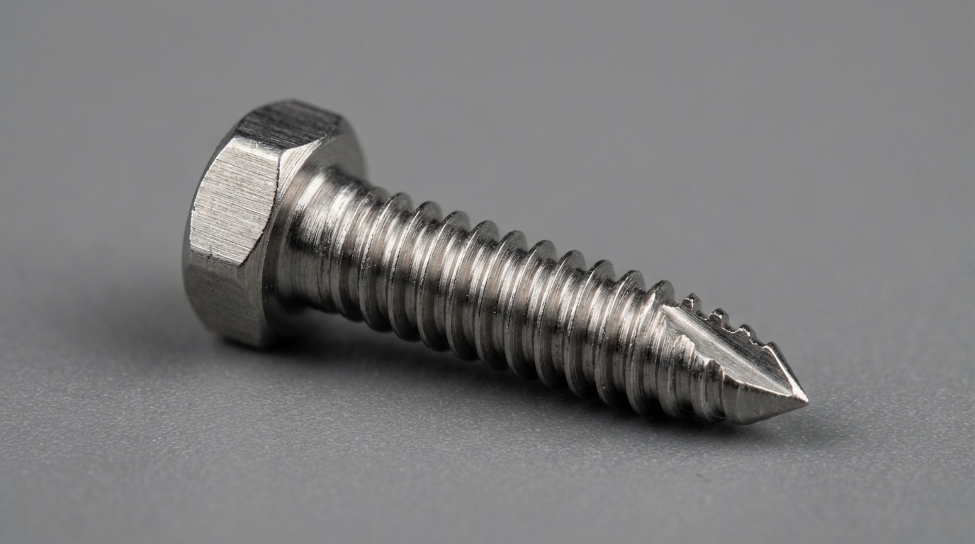
Orthodontic micro-implants (also known as Temporary Anchorage Devices or TADs) are critical miniature implantable devices used in orthodontic treatment to provide absolute anchorage force for assisted tooth movement. Unlike conventional orthodontic appliances that rely on the patient’s own teeth for anchorage, micro-implants are directly inserted into the alveolar bone as independent anchorage units, enabling complex tooth movements that are difficult or impossible with traditional methods — such as full-arch retraction, molar intrusion for deep bite correction, and severe space closure. According to ISO 6475 / YY/T 0316 standards, common specifications range from M1.5-M3 outer diameter, with precision grade requirements of 4H, and thread diameters as small as only 1.5-2mm. These are widely recognized as some of the most challenging precision components in medical device micro-machining.
Application Scenarios
Orthodontic micro-implants are primarily applied in the orthodontic medical field, covering a variety of complex malocclusion treatment scenarios. Based on specific implantation positions and functional requirements, different application scenarios impose the following differentiated requirements:
– Anterior Retraction: Micro-implants placed in the buccal alveolar ridge or palatal region, with elastic traction assisting full-arch anterior retraction. This is one of the most effective methods for resolving bimaxillary protrusion. Common specification is 2mm x 8mm, requiring stable thread purchase without loosening under sustained orthodontic force (approximately 1.5-2.5N).
– Molar Intrusion: Placed in the buccal or palatal furcation area of molars to intrude over-erupted molars and reestablish the occlusal plane. Threads must precisely seat within the narrow furcation space, imposing extremely high requirements on screw diameter and thread profile precision.
– Molar Distalization: Placed in the palatal midline or below the zygomatic arch, using micro-implants as anchorage to push molars distally. Alveolar cortical bone thickness is only 1-2mm, and insertion torque must be precisely controlled within 5-15 Ncm — excessive torque causes bone micro-damage or even implant failure.
All application scenarios impose strict requirements on the reliability of orthodontic micro-implant threaded connections, because thread loosening or failure leads to anchorage loss, treatment failure, or even bone perforation — serious clinical complications that may require removal and re-implantation, extending treatment duration and increasing patient discomfort.
Structural Characteristics
Orthodontic micro-implants have the following structural characteristics:
– Ultra-Small Diameter Long-Shank Structure: Thread outer diameter is only 1.5-2mm, but length reaches 8-12mm, giving length-to-diameter ratios of 6:1 to 8:1. Such slender threaded shanks have extremely poor rigidity during machining, and conventional lathes cannot grip them at all. This is the most fundamental characteristic distinguishing them from other threaded components.
– Integrated Head Drive and Threaded Shank: The screw head typically features a cross-slot or internal hex drive structure, slightly larger than the thread outer diameter (2.5-3mm), integrated with the threaded shank. The transition from head to thread requires a smooth radiused profile to avoid stress concentration.
– Self-Tapping Thread Design: The leading portion of micro-implant threads typically incorporates 1-3 cutting flutes, allowing direct insertion into bone tissue without pre-drilling. Thread profiles are often asymmetrical — the proximal portion has deeper threads for primary stability, while the distal portion has shallower threads for easier insertion. The varying thread profiles across different sections place extremely high demands on machining precision.
– Material Requirements: TC4 titanium alloy (Ti-6Al-4V ELI), complying with GB/T 13810 / ASTM F136 standards. Offers excellent biocompatibility, high strength (tensile strength >= 860 MPa), and corrosion resistance, but with moderate hardness (HRC 30-36) and extremely low thermal conductivity (only 1/6 that of 45 steel), making it a classic difficult-to-machine material.
– Surface Quality: Thread flank surface roughness Ra0.4 (mirror finish). Thread surfaces must not retain machining burrs or tooling marks. Thread surface quality directly affects osseointegration outcomes — rough surface patterns can prolong the bone integration period and increase infection risk.
Key Features
Key Characteristics:
– High Precision Machining: Supports 4H precision grade, with pitch diameter tolerance controlled within +/-0.003mm for M2 specification, meeting ISO 6475 medical device miniature thread standards.
– High Efficiency Production: Suitable for mass production. Swiss-type lathe with miniature whirlwind milling achieves cycle times of 15-25 seconds per piece, with daily capacity exceeding 3,000 pieces. Fully automated continuous production is achievable with Swiss-type lathe integration.
– Quality Assurance: Complies with GB/T 13810 / ASTM F136 titanium alloy material standards and ISO 6475 surgical implant thread standards. Full inspection via coordinate measuring machines (CMM) and precision thread gauges with complete product traceability.
Thread Technical Parameters
| Item | Parameter Range | Notes |
|---|---|---|
| Thread Specification | M1.5-M3 | Asymmetrical self-tapping thread, metric triangular thread |
| Precision Grade | 4H | ISO 6475 / GB/T 2281 |
| Thread Length | 4-8mm | Determined by implant model and implantation site |
| Thread Outer Diameter | 1.5-2mm | Ultra-small diameter, length-to-diameter ratio 6:1-8:1 |
| Surface Roughness | Ra0.4 | Thread flanks (mirror-finish requirement) |
| Thread Profile Angle Precision | +/-15′ | 60-degree metric triangular thread |
| Material | TC4 (Ti-6Al-4V ELI) | GB/T 13810 / ASTM F136 |
| Production Efficiency | 15-25 sec/piece | Swiss-type lathe + miniature external whirlwind milling |
Why Whirlwind Milling is the Preferred Process for Orthodontic Micro-Implants
Conventional Process Pain Points
Orthodontic micro-implants face the following severe challenges when using conventional turning for thread machining:
| Pain Point | Specific Issue | Impact |
|---|---|---|
| 1.5mm Ultra-Small Diameter Cannot Be Gripped | Minimum grip diameter for conventional lathe 3-jaw chucks is approximately 3mm. 1.5mm workpieces cannot be clamped at all | Conventional turning completely unable to machine; only Swiss-type lathe or external grinding possible |
| Severe Turning Chatter Marks | Length-to-diameter ratio of 6:1-8:1 slender shanks generate severe vibration during turning, thread surface covered in chatter marks, unable to achieve Ra0.4 | Surface quality fails to meet medical implant requirements |
| Extremely Short Insert Life | TC4 titanium alloy has poor thermal conductivity; turning 1.5mm threads concentrates heat at tool tip, insert failure after only 5-10 pieces | Extremely high tooling costs, frequent tool changes severely impact efficiency |
| Excessive Cycle Time | Conventional turning requires multiple passes for gradual thread forming at 1.5mm diameter, taking 5-8 minutes per piece | Severely insufficient capacity, unable to meet mass production requirements |
Whirlwind Milling Process Advantages
Addressing the above pain points, Swiss-type lathe with miniature external whirlwind milling provides systematic solutions:
| Comparison Dimension | Conventional Turning | Swiss-type Lathe + Miniature Whirlwind Milling | Improvement |
|---|---|---|---|
| Machining Efficiency | 300-480 sec/piece | 15-25 sec/piece | 15-20x efficiency improvement |
| Surface Quality | Ra1.6-Ra3.2 | Ra0.4 (mirror finish) | Over 75% roughness reduction |
| Insert Life | 5-10 pieces/insert | 1000-1500 pieces/insert | Over 100x insert life improvement |
| Defect Rate | 20%+ | <=0.3% | 98% defect rate reduction |
| Precision Grade | Unable to machine | Stable 4H | Achieves ultra-small diameter 4H precision |
Core Advantages:
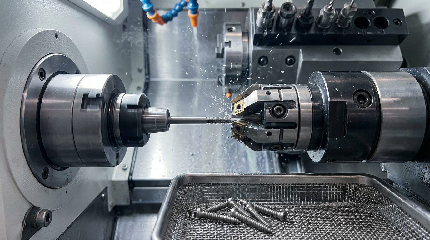
– Guide Bushing Close-Support Machining: The core advantage of Swiss-type lathes is guide bushing close-support machining. For ultra-small diameter workpieces of 1.5-2mm, conventional lathes cannot grip them at all. The Swiss-type lathe provides continuous rigid support through the guide bushing directly below the cutting point, with the cutting point always adjacent to the guide bushing exit, achieving zero-overhang machining. This fundamentally solves the clamping challenge for ultra-small diameter workpieces.
– Multi-Insert Single-Pass Forming: The whirlwind milling miniature cutter head rotates at high speed with multiple inserts cutting simultaneously, completing the entire thread profile of 1.5mm micro-threads in a single pass. Symmetrically distributed inserts cancel radial cutting forces against each other, with resultant force approaching zero. Even slender shanks undergo virtually no bending deformation during machining.
– Interrupted Cutting Low-Temperature Machining: In whirlwind milling interrupted cutting mode, tool-to-workpiece contact time is less than 15% of total time, with most cutting heat carried away by chips. Combined with high-pressure internal coolant (oil-based cutting fluid) flushing, tool tip temperature remains far below continuous cutting levels, effectively suppressing TC4 tool galling while significantly extending insert life while maintaining Ra0.4 mirror-finish surface quality.
Thread Machining Process
This machining process uses 8 processes to complete orthodontic micro-implant thread manufacturing, covering the entire production workflow from raw material cutting to finished product inspection and packaging. The core process is Step 6 Whirlwind Milling, using a Swiss-type CNC sliding head lathe with a miniature whirlwind milling power head to form micro-implant threads in a single pass, improving efficiency by 15-20x compared to conventional turning. Processes 1-5 are the preparation and pre-machining stage, process 6 is thread machining, and processes 7-8 are post-processing and inspection.
Complete Process Flow
| Process | Process Name | Equipment | Tool | Time | Precision |
|---|---|---|---|---|---|
| 01 | Cutting | Swiss-type Lathe | Parting Tool | 2 sec | +/-0.05mm |
| 02 | Face Machining | Swiss-type Lathe | Face Turning Tool | 1 sec | Perpendicularity <=0.01mm |
| 03 | Head Forming | Swiss-type Lathe | Forming Tool/Milling Cutter | 2-3 sec | +/-0.01mm |
| 04 | OD Finish Turning | Swiss-type Lathe | Finish Turning Insert | 2-3 sec | +/-0.003mm |
| 05 | Self-Tapping Flute Machining | Swiss-type Lathe | Slotting Tool/Milling Cutter | 1-2 sec | +/-0.02mm |
| 06 | Whirlwind Milling | Swiss-type Lathe + Whirlwind Head | Miniature Whirlwind Cutter Head | 5-8 sec | 4H Precision |
| 07 | Deburring | Swiss-type Lathe / Electropolishing | Deburring Tool | 2 sec | – |
| 08 | Inspection | CMM / Vision Measuring System | Precision Thread Gauges | 20-40 sec | – |
Process Descriptions
Step 1: Cutting
Process Purpose: Cut TC4 titanium alloy bar stock to the specified length per process requirements, using Swiss-type lathe guide bushing feed, preparing for all subsequent machining operations.
Key Points:
– The Swiss-type lathe spindle clamps the bar stock, feeds through the guide bushing, and the parting tool cuts off the piece, ensuring a flat cut surface
– Control cutting length tolerance within +/-0.05mm, with single-piece cutting time of approximately 2 seconds
– Use TC4 titanium alloy bar stock meeting GB/T 13810 standards (2.5mm or 3mm diameter), with complete material certificates and batch traceability
– Inspect material surface quality for cracks, inclusions, laps, and other defects. Material hardness HRC 30-36
Quality Standards:
– Length dimension meets drawing requirements, tolerance +/-0.05mm
– Cut end face is flat with no significant burrs
– Material identification is clear and traceable, material certificates complete
Step 2: Face Machining
Process Purpose: Machine the workpiece end face to ensure flatness and perpendicularity to the axis, providing a precise datum for subsequent head forming and OD finish turning.
Key Points:
– Ensure end face perpendicularity to axis <=0.01mm, meeting subsequent micro-machining coaxiality requirements
– Control end face roughness Ra<=0.8, with flat end face free of vibration marks
– Complete end face machining in a single clamping to ensure consistent datum with the axis
– Use PCD or coated carbide face turning tools suitable for TC4 micro-cutting requirements
Quality Standards:
– End face is flat, free of vibration marks and tool marks
– Perpendicularity <=0.01mm, meeting miniature medical device datum requirements
– Surface roughness meets standards, end face is smooth
Step 3: Head Forming
Process Purpose: Machine the micro-implant head structure, including the cross-slot or internal hex drive hole and the transition radius from head to threaded shank. This is a critical process unique to micro-implants. The head design directly affects the clinical efficiency of insertion torque transfer.
Key Points:
– Head diameter is 2.5-3mm, slightly larger than the thread outer diameter, formed in a single operation using a forming tool or miniature milling cutter
– Cross-slot or internal hex slot depth precision controlled within +/-0.01mm, slot wall roughness Ra<=1.6, ensuring accurate engagement with orthodontic drivers
– Transition radius from head to threaded shank is R0.3-0.5mm, must be smooth without tool marks to avoid stress concentration
– Transition zone dimensions must be precisely controlled, directly affecting thread start completeness and initial insertion torque into bone tissue
– Guide bushing provides close support throughout the process, ensuring head-to-shank coaxiality <=0.01mm
Quality Standards:
– Head drive slot dimensions are precise, engaging smoothly with orthodontic drivers
– Transition radius is smooth, without steps or tool marks
– Head-to-shank coaxiality <=0.01mm
Step 4: OD Finish Turning
Process Purpose: Finish turn the threaded shank outer diameter to final dimension, achieving required dimensional precision and surface roughness. Ensure coaxiality and cylindricity of the threaded portion, providing a precise OD datum for Step 6 whirlwind milling.
Key Points:
– Control finishing allowance at 0.05-0.1mm, using extremely small depth of cut and low feed rate strategy
– The Swiss-type lathe guide bushing closely supports the workpiece OD during machining. The cutting point is always near the guide bushing support, which is especially critical for ultra-small 1.5-2mm diameter workpieces
– Ensure OD tolerance +/-0.003mm, roughness Ra<=0.4, cylindricity <=0.003mm
– The finish-turned OD dimension serves as the basis for thread major diameter. M2 thread major diameter tolerance is only +/-0.003mm, requiring strict control
– Use nano-coated carbide inserts (e.g., TiAlN coating) with tool nose radius <=0.1mm, suitable for micro-diameter finish turning
Quality Standards:
– OD dimensional precision +/-0.003mm, meeting micro-thread tolerance requirements
– Surface is mirror-smooth, free of tool marks and vibration marks
– Cylindricity <=0.003mm, coaxiality <=0.005mm
– OD diameter consistency, stable tolerance between batches
Step 5: Self-Tapping Flute Machining
Process Purpose: Machine 1-3 self-tapping cutting flutes at the leading portion of the micro-implant thread, allowing the screw to be directly inserted into bone tissue without pre-drilling. Flute shape, depth, and angle directly affect insertion torque and bone debris evacuation efficiency.
Key Points:
– Flutes are typically located within the first 1-3 thread pitches of the screw tip, machined using a miniature slotting tool or end mill
– Flute depth is approximately 60-80% of thread depth — too deep weakens thread strength, too shallow provides insufficient self-tapping capability
– Flute angle matches the thread helix angle (typically 60-75 degrees), ensuring cutting edge sharpness
– Flute root radius R0.1-0.2mm, avoiding stress concentration that could cause thread fracture
– Flute wall roughness Ra<=1.6, smooth flute walls facilitate bone debris evacuation
Quality Standards:
– Flute position and depth meet design requirements
– Flute walls are smooth, free of burrs and tearing
– Flutes do not damage adjacent thread profiles
Step 6: Whirlwind Milling
Process Purpose: Use miniature external whirlwind milling to form the complete micro-implant thread profile in a single pass, achieving 4H precision grade and Ra0.4 mirror-finish surface roughness. This is the most critical process in the entire manufacturing sequence.
Process Principle: The whirlwind milling power head is mounted on the Swiss-type lathe tool post. A miniature cutter head (typically 15-25mm diameter) holds multiple carbide inserts. The cutter head rotates at high speed (5000-8000 rpm) while the workpiece rotates at low speed (20-40 rpm). Inserts traverse the workpiece along the helical path, completing the 1.5-2mm micro-thread profile in a single pass. Ultra-small diameter workpieces require higher cutter head speeds to achieve sufficient cutting velocity, combined with extremely low workpiece speed to ensure precise thread pitch control.
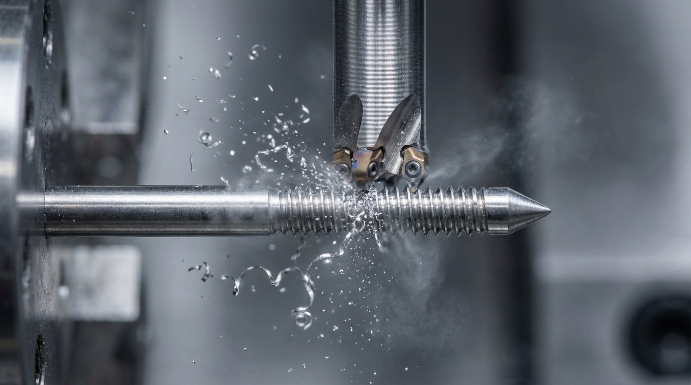
Key Points:
– Power head speed 5000-8000 rpm, C-axis (workpiece) speed 20-40 rpm, maintaining proper speed ratio
– Miniature cutter head holds 2-4 inserts, indexing error <=0.3 degrees, ensuring multi-insert cutting uniformity
– Feed rate matches thread pitch requirements (M1.5 pitch 0.35mm, M2 pitch 0.4mm)
– High-pressure internal coolant (80-120 bar oil-based cutting fluid) flushes the cutting zone for effective chip evacuation and cooling
– Swiss-type lathe guide bushing provides close support, with cutting point extremely close to the guide bushing support, achieving zero deflection deformation
Common Issues and Solutions:
– Chatter Marks/Vibration: Ultra-small diameter workpiece insufficient rigidity -> Ensure guide bushing is not worn, minimize workpiece overhang, appropriately reduce workpiece speed
– Pitch Diameter Out of Tolerance: Insert wear or cutter head eccentricity -> Regularly inspect pitch diameter, establish tool wear compensation, calibrate cutter head dynamic balance
– Poor Surface Roughness: Improper cutting parameters or insufficient cooling -> Adjust power head speed, check coolant pressure and flow
Quality Standards:
– Thread pitch diameter tolerance complies with 4H grade (M2 specification: +/-0.003mm)
– Cumulative pitch error <=0.005mm
– Thread flank surface roughness Ra0.4, mirror finish, free of burrs and chatter marks
– Correct thread profile angle, complete full thread form
Step 7: Deburring
Process Purpose: Remove machining burrs from thread ends, self-tapping flute edges, and the head drive slot, ensuring micro-implant appearance quality and clinical safety. Medical device miniature component deburring requirements are extremely stringent.
Key Points:
– Use miniature deburring chamfer tools mounted on the Swiss-type lathe to simultaneously complete thread end chamfering and deburring during the machining cycle
– Thread leading and trailing ends must form complete lead-in and run-out angles, ensuring smooth insertion into bone tissue without resistance
– Self-tapping flute edge burrs must be thoroughly removed. Residual burrs can scratch bone tissue and increase insertion torque
– Burrs inside the head drive slot must be cleaned with miniature tools to ensure accurate orthodontic driver engagement
– Supplementary ultrasonic deburring or electropolishing can be used for secondary fine cleaning of microscopic burrs
– Medical implant standard requirements: all sharp edges broken to R0.05-0.1mm, completely smooth to touch
Quality Standards:
– No visible burrs or sharp edges under 10x magnification
– Thread crests are complete, with no profile damage from excessive chamfering
– Flute edges are smooth, free of burrs and metal rollover
– Clean appearance, consistent smooth surface
Step 8: Inspection
Process Purpose: Conduct comprehensive quality inspection on orthodontic micro-implants, covering thread precision, dimensional parameters, surface quality, and material properties. Qualified products are packaged per medical-grade standards and stored.
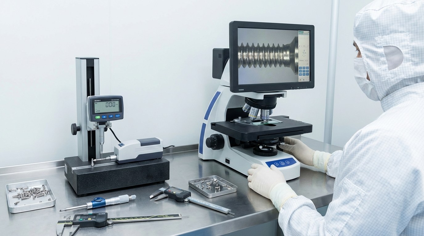
Key Points:
– Use high-precision coordinate measuring machine (CMM) to inspect thread pitch diameter, pitch, thread half-angle, major diameter, minor diameter, and all other parameters
– Use precision thread GO/NO-GO gauges for rapid 100% full inspection
– Vision measuring system (VMS) at 200-400x magnification inspects miniature thread profile completeness, excluding chipped teeth, defects, etc.
– Surface roughness tester measures thread flank roughness. Medical components require Ra<=0.4
– Optical comparator inspects self-tapping flute position, depth, and angle to verify compliance with design specifications
– Insertion torque testing: sample testing in polyurethane bone simulation blocks to verify insertion torque falls within the clinical range of 5-15 Ncm
– First piece mandatory inspection, process sampling rate >=10%, key batches full inspection
Quality Standards:
– Thread precision meets 4H grade requirements, GO/NO-GO gauge inspection passed
– All dimensional parameters meet product drawing tolerance requirements
– Surface roughness Ra0.4 meets standards, no burrs or defects
– Each piece includes quality certificate, packaging complies with ISO 11607 medical packaging standards
– Complete batch records, enabling full quality traceability
Machining Difficulties and Solutions
Difficulty 1: Ultra-Small Diameter (1.5-2mm) Thread Machining
Problem Description:
– Orthodontic micro-implant thread diameter is only 1.5-2mm with length-to-diameter ratios of 6:1-8:1, resulting in extremely poor radial rigidity. The minimum grip diameter for conventional lathe chucks is approximately 3mm, making 1.5mm workpieces impossible to clamp. Even with spring collets, the overhanging section bends severely under cutting force, and chatter marks cannot be eliminated.
– Machining a 0.35mm pitch micro-thread on a 1.5mm outer diameter means the cutting area per individual pitch is extremely small (approximately 0.015mm2). Conventional single-point turning struggles to control such tiny cutting allowances,极易 leading to tool chattering and incomplete thread profiles.
Solutions:
– Swiss-type lathe guide bushing close-support machining is the only viable solution for the ultra-small diameter clamping challenge. Bar stock passes through the spindle and guide bushing, with the cutting point always located directly below the guide bushing exit (less than 1mm from the support point). The workpiece achieves maximum rigidity in the cutting zone. Even 1.5mm diameter workpieces do not produce perceptible bending deformation under guide bushing support.
– Miniature whirlwind milling cutter heads (15-25mm diameter) rotate at 5000-8000 rpm, combined with extremely low workpiece speeds of 20-40 rpm. This ensures sufficient cutting velocity (insert linear speed approximately 60-100 m/min) while achieving precise pitch control. Multiple inserts cutting simultaneously cancel radial forces, with resultant force approaching zero.
– Inserts use ultra-fine grain carbide (grain size <=0.5 micrometers) with TiAlN nano-coating, tool nose radius of only 0.02-0.03mm, capable of precisely forming every detail of the 1.5mm micro-thread profile.
– Effect: The Swiss-type lathe + miniature whirlwind milling solution successfully achieves stable 4H precision machining of 1.5mm diameter, 0.35mm pitch micro-threads, with defect rate <=0.3% and surface roughness Ra0.4 achieving mirror-finish quality.
Difficulty 2: Ra0.4 Mirror-Finish Surface Quality Assurance
Problem Description:
– As oral implants, orthodontic micro-implant thread surface quality directly affects osseointegration outcomes. Clinical requirements specify thread flank roughness of Ra0.4, achieving mirror-finish quality. Conventional turning on TC4 titanium alloy typically produces thread surface roughness of only Ra1.6-Ra3.2, with surfaces covered in tool marks and chatter marks.
– TC4 titanium alloy has extremely low thermal conductivity (7.9 W/mK). Cutting heat concentrates in the cutting zone and cannot dissipate quickly. High temperatures cause titanium alloy surface oxidation discoloration and work hardening, further degrading surface quality. Ultra-small diameter workpieces have minimal heat dissipation area, making heat accumulation even more problematic.
Solutions:
– In whirlwind milling interrupted cutting mode, each insert contacts the workpiece for only 10-15% of total cutting time, with most cutting heat carried away by the high-speed ejected chips. Heat transferred to the workpiece is minimal. Compared to conventional turning continuous cutting mode, workpiece temperature rise is reduced by over 60%.
– Combined with 80-120 bar high-pressure internal coolant (oil-based cutting fluid), coolant is delivered through the whirlwind milling cutter head internal channels directly to the cutting zone, forming a cooling lubrication film at the insert-workpiece interface. This both reduces cutting temperature and minimizes friction. Oil-based cutting fluid provides superior lubrication compared to water-based, contributing to smoother machined surfaces.
– Optimized cutting parameters: higher cutter head speeds (5000-8000 rpm) reduce feed per tooth to extremely small values, with each insert removing only an ultra-thin layer of metal per engagement, producing very shallow cutting marks. Lower workpiece speeds (20-40 rpm) combined with precise pitch synchronization ensure uniform coverage of the machined trajectory on the workpiece surface.
– Effect: Thread flank roughness stably achieves Ra0.4 mirror-finish, with surfaces free of oxidation discoloration and work-hardened layers. Thread surface quality fully meets the clinical requirements for orthodontic micro-implant osseointegration. No post-machining polishing or surface treatment is required.
Manufacturing Case
Customer Background
A well-known domestic orthodontic equipment manufacturer specializing in the research, development, and production of orthodontic micro-implants, brackets, archwires, and other orthodontic products, with annual production of approximately 500,000 micro-implants. With the rapid growth of the invisible orthodontics market, customers imposed higher requirements for micro-implant capacity and quality, and conventional machining processes could no longer meet delivery demands.
Technical Challenges
- For 1.8mm diameter micro-implants, conventional turning scrap rate exceeded 20%, primarily manifesting as thread chatter marks, thread profile defects, and diameter out-of-tolerance
- TC4 titanium alloy caused turning insert life of only 5-10 pieces. Frequent tool changes severely impacted production capacity, with monthly capacity of only 30,000-40,000 pieces
- Single-piece machining time of 5-8 minutes failed to meet the annual production target of 500,000 pieces. Customer orders were severely backlogged
- Unstable thread precision with surface roughness Ra1.6-Ra3.2, unable to meet premium customers’ Ra0.4 requirements
Solutions
| Item | Parameters/Configuration |
|---|---|
| Workpiece Name | Orthodontic Micro-Implant (M2x0.4, length 10mm) |
| Thread Specification | M1.5-M3, 4H Precision |
| Material | TC4 Titanium Alloy (Ti-6Al-4V ELI), GB/T 13810 |
| Equipment | Swiss-type CNC Sliding Head Lathe + Miniature Whirlwind Milling Power Head |
| Cutter Head | Miniature whirlwind cutter head, 20mm diameter, 4 TiAlN-coated inserts |
| Processes | 8 integrated processes: cutting – facing – head forming – finish turning – self-tapping flute – whirlwind milling – deburring – inspection |
| Precision | Thread 4H precision, pitch diameter M2 +/-0.003mm, Ra0.4 |
| Efficiency | Cycle time 18 sec/piece, daily capacity approximately 3,200 pieces |
| Cost | Per-piece tooling cost reduced by 95%, scrap rate reduced by 98% |
Implementation Results
- Single-piece cycle time reduced from 5-8 minutes to 18 seconds, an approximately 15x production efficiency improvement
- Scrap rate reduced from 20%+ to 0.3%, saving approximately 600,000 RMB annually in TC4 material costs
- Thread precision consistently achieved 4H grade, with surface roughness Ra0.4 achieving mirror-finish quality, eliminating the polishing process
- Whirlwind milling insert life reached 1000-1500 pieces, with per-piece tooling cost reduced by over 95%
- Annual capacity increased from 300,000 to over 500,000 pieces, fully meeting order delivery requirements
Customer Testimonial
“The Swiss-type lathe with whirlwind milling process has completely resolved our micro-implant production bottleneck. Previously, the high scrap rate for 1.8mm thread machining made us hesitant to accept large orders. Now, not only has the scrap rate dropped to three per thousand, but our efficiency has increased fifteenfold. What satisfies us most is that the thread surface quality directly achieves a mirror finish, eliminating the original manual polishing process. Both quality and efficiency have undergone a qualitative leap.”
Common Questions
Q1: What process is most suitable for orthodontic micro-implant thread machining?
Recommended process based on annual production volume and precision requirements:
| Annual Volume | Recommended Process | Single Piece Time | Precision | Application |
|---|---|---|---|---|
| <10,000 | CNC Turning (Swiss-type single-point turning) | 300-480 sec | 6H-7H | Prototyping, small batch custom |
| 10,000-100,000 | Swiss-type Lathe Turning + Polishing | 60-120 sec | 6H | Medium batch production |
| >100,000 | Swiss-type Lathe + Miniature Whirlwind Milling | 15-25 sec | 4H | Large-scale mass production |
Conclusion: For mass production of orthodontic micro-implants with annual volumes above 100,000 pieces, Swiss-type lathe with miniature whirlwind milling power head is the optimal choice, balancing efficiency, precision, and cost.
Q2: What precision can whirlwind milling achieve for orthodontic micro-implants?
Miniature external whirlwind milling for orthodontic micro-implants can achieve:
– Precision Grade: Stable 4H (ISO 6475 / ISO 965), with M2 specification pitch diameter tolerance of +/-0.003mm
– Surface Roughness: Thread flanks Ra0.4 (mirror finish), root Ra1.6-Ra3.2
– Pitch Error: Cumulative pitch error <=0.005mm
– Thread Profile Angle Precision: +/-15′ (60-degree metric triangular thread)
– Coaxiality: Thread to OD coaxiality <=0.005mm
Key factors affecting precision:
– Swiss-type lathe spindle precision and guide bushing wear condition (guide bushing ID wear >0.005mm requires replacement)
– Whirlwind milling cutter head dynamic balance precision and insert indexing accuracy
– TC4 material batch consistency
– High-pressure cooling system pressure and flow stability
– Workshop temperature control (recommended 20+/-2 degrees C constant temperature room)
Q3: What is the cycle time for orthodontic micro-implant whirlwind milling thread machining?
Typical cycle time breakdown (M2 micro-implant, 6mm thread length):
| Process | Time |
|---|---|
| Cutting | 2 seconds |
| Face Machining | 1 second |
| Head Forming | 2-3 seconds |
| OD Finish Turning | 2-3 seconds |
| Self-Tapping Flute Machining | 1-2 seconds |
| Whirlwind Milling | 5-8 seconds |
| Deburring | 2 seconds |
| Inspection (sampling) | 20-40 seconds |
| Total (excluding inspection) | 15-21 seconds |
Total Cycle Time: Approximately 15-25 seconds per piece (excluding inspection), 35-65 seconds per piece including inspection. Multi-station synchronized machining on Swiss-type lathe can further compress total cycle time.
Q4: What is whirlwind milling tool cost for orthodontic micro-implants? What about tool life?
Tool cost reference for machining TC4 titanium alloy orthodontic micro-implants:
– Miniature Cutter Head (body): 3,000-5,000 RMB/set (reusable, service life approximately 2 years)
– Coated Carbide Inserts: 20-40 RMB/insert (micro-diameter specialty inserts with high precision requirements)
– Insert Life: Approximately 1,000-1,500 pieces/insert when machining TC4
– Tool Cost Per Piece: Approximately 0.015-0.03 RMB/piece (insert cost only)
Factors affecting TC4 micro-machining tool life:
– TC4 material hardness batch variation (HRC 30-36)
– High-pressure coolant type and pressure (oil-based superior to water-based)
– Whether cutter head speed and workpiece speed matching is optimized
– Insert coating type (TiAlN/AlCrN superior to TiN)
– Guide bushing support condition (poor support accelerates insert wear and chipping)
Q5: What advantages does whirlwind milling have over conventional thread turning?
Taking orthodontic micro-implant (TC4, M2x0.4, 1.8mm diameter) machining as an example:
| Comparison Item | Swiss-type Lathe + Miniature Whirlwind Milling | Conventional Turning |
|---|---|---|
| Cycle Time | 15-25 sec/piece | 300-480 sec/piece |
| Thread Precision | Stable 4H | Unable to machine / 6H-7H |
| Surface Roughness | Ra0.4 (mirror finish) | Ra1.6-Ra3.2 |
| Insert Life | 1000-1500 pieces/insert | 5-10 pieces/insert |
| Tool Cost Per Piece | 0.015-0.03 RMB | 2-5 RMB |
| Defect Rate | <=0.3% | 20%+ |
| Post-Machining Polishing | Not required | Required |
| Operator Skill Requirement | Automatic operation after programming | Extremely high (depends on technician experience) |
| Adaptability | Suitable for mass production | 1.5mm diameter completely unable to machine |
Conclusion: For mass production of TC4 orthodontic micro-implants at 1.5-2mm diameter, Swiss-type lathe + miniature whirlwind milling is the only viable high-precision, high-efficiency solution. Conventional turning is virtually unable to complete machining at 1.5mm diameter. Whirlwind milling not only solves the machining feasibility challenge but also achieves a qualitative leap in efficiency and quality.
Q6: How to improve production efficiency in orthodontic micro-implant thread machining?
Efficiency improvement measures:
Equipment Aspect:
– Use multi-spindle Swiss-type lathes for multi-station synchronized machining, producing multiple pieces per cycle
– Configure automatic loading/unloading robots to reduce handling time
– Select high-precision miniature whirlwind milling power heads and high-rigidity guide bushings to improve machining stability and speed
Process Aspect:
– Optimize whirlwind milling cutting parameters to maximize feed rate while maintaining Ra0.4 surface quality
– Design combined operations: cutting, facing, head forming, finish turning, flute machining, and whirlwind milling completed in a single clamping
– Establish tool life management system for predictive tool replacement, avoiding unplanned downtime
Management Aspect:
– Implement SPC (Statistical Process Control) for real-time pitch diameter data and surface roughness trend monitoring
– Establish SMED (Single-Minute Exchange of Die) procedures to minimize changeover time
– Preventive maintenance schedules, particularly for guide bushing and spindle regular inspection and replacement
– Full-process quality traceability system to reduce rework and scrap at the source
Results: Cycle time can be reduced to under 15 seconds per piece, daily capacity improved by over 30%, and overall efficiency improved by 40-50%.
Summary
Orthodontic micro-implant thread machining using Swiss-type lathe with miniature external whirlwind milling can achieve 4H precision grade, with single-piece cycle time of approximately 15-25 seconds, suitable for large-scale mass production of 100,000+ pieces annually. Three major technical advantages — Swiss-type lathe guide bushing close-support solving the 1.5-2mm ultra-small diameter clamping challenge, whirlwind milling multi-insert symmetric balanced cutting force achieving zero-deformation machining of slender shanks, and interrupted cutting low-temperature mode ensuring Ra0.4 mirror-finish surface quality — perfectly solve the three core challenges in orthodontic micro-implant micro-machining: clamping, deformation, and surface quality. For orthodontic equipment manufacturers with annual production of 100,000 pieces or more, the Swiss-type lathe + miniature whirlwind milling solution is the best choice for balancing efficiency, quality, and cost. It is also currently the only mature process route capable of stably achieving 4H precision on 1.5mm micro-threads.
If you are facing orthodontic micro-implant machining challenges (such as ultra-small diameter unable to be gripped for machining, surface roughness failing to meet standards, insufficient capacity causing delivery delays), or looking to improve thread machining precision and surface quality while reducing production costs, contact us to get customized machining solutions.