Dental implants are the most technically demanding implantable devices in the field of oral rehabilitation. Their external threads must screw into the alveolar bone to achieve osseointegration, while internal threads connect the abutment and crown to restore chewing function. Implant thread quality directly determines osseointegration success rate and long-term stability. The extremely low thermal conductivity and strong chemical affinity of TC4 titanium alloy cause serious challenges for traditional turning, including tool tip burnout, built-up edges, and substandard surface quality. Micro external thread whirling, with its low-temperature interrupted cutting characteristics and guide bushing rigid support, has become the preferred solution for precision machining of dental implant internal and external threads.
What Are Dental Implants
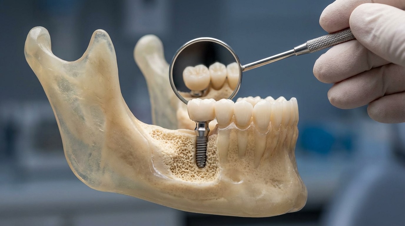
Dental implants are artificial tooth roots surgically placed into the alveolar bone, forming osseointegration with bone tissue through external threads to provide stable support for supra-structures, currently the preferred solution for tooth replacement.
Application Scenarios
| Restoration Type | Typical Implant Specification | Applicable Site |
|---|---|---|
| Single Tooth Replacement | φ3.3-4.5mm, L8-12mm | Anterior/Posterior Region |
| Multiple Teeth Bridging | φ3.5-5.0mm, L10-14mm | Free-End / Edentulous Space |
| Full Arch Rehabilitation | φ4.0-5.0mm, L10-16mm | Maxilla / Mandible |
| Immediate Implant Placement | φ3.5-4.5mm, L8-14mm | Fresh Extraction Socket |
| Augmented Bone Region | φ3.3-4.0mm, L6-10mm | Insufficient Bone Volume |
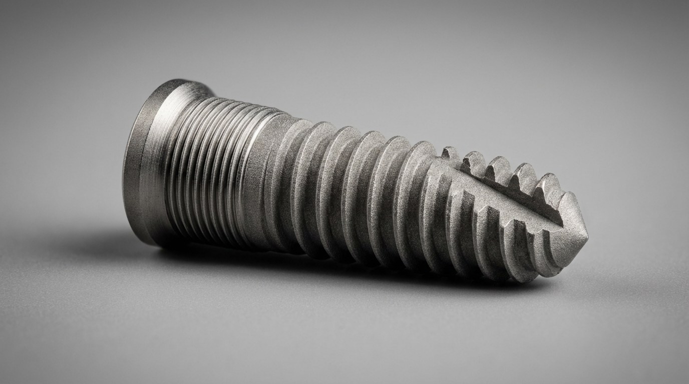
Structural Characteristics
Dental implants feature the most complex thread structure among all implantable devices:
- Precision dual internal/external threads: External self-tapping bone engagement thread (M2-M4) and internal abutment connection thread (typically M1.5-M2.5), with extremely tight coaxiality requirement (≤0.01mm)
- Variable pitch design: Denser pitch at the neck for primary stability, gradually increasing pitch toward the apex to reduce insertion torque, requiring single-pass forming
- Micrometer-level surface texture: External thread surface requires precision base texture prior to SLA (sandblasted, large-grit, acid-etched) or anodizing treatment, where roughness directly affects osseointegration speed
- Biocompatibility coating substrate: Thread surface must be free of any machining defects and contamination layers, otherwise affecting hydroxyapatite coating or titanium plasma spray adhesion
Key Characteristics of Dental Implants
- Primary stability: Provided by mechanical interlocking of threads with bone tissue at the moment of implant placement; thread major diameter, pitch, and profile angle accuracy directly affect primary stability
- Osseointegration capability: Thread surface morphology (roughness, thread depth, pitch) determines osteoblast attachment and proliferation rate on the implant surface
- Long-term load-bearing reliability: Under hundreds of thousands of mastication cycles annually, the smoothness of thread root fillet radius determines fatigue life
Dental Implant Thread Technical Parameters
| Parameter | External Osseointegration Thread | Internal Abutment Connection Thread |
|---|---|---|
| Thread Specification | M2-M4 (external) | M1.5-M2.5 (internal) |
| Pitch | 0.6-1.2mm (variable) | 0.35-0.45mm |
| Accuracy Class | 4H | 4H |
| Surface Roughness | Ra0.4-1.6 (osseointegration zone) | Ra0.4-0.8 |
| Profile Angle | V-type/Square-type/Saw-type | 60° standard metric |
| Coaxiality Requirement | Internal/external thread coaxiality ≤0.01mm | — |
| Material Standard | ASTM F136 / ISO 5832-3 (TC4 ELI) | Same |
| Cycle Time (Whirling) | 25-40 seconds (external thread) | — |
| Inspection Standard | ISO 14801 / FDA 510(k) | — |
Why Thread Whirling Is the Preferred Process for Dental Implants
Core Pain Points of Traditional Turning
| Pain Point | Specific Manifestation | Consequence |
|---|---|---|
| Tool Tip Burnout | TC4 ELI ultra-low carbon titanium alloy heat concentration, tool tip >1000°C | Insert life 5-15 pieces; frequent tool changes cause batch accuracy fluctuation |
| Internal/External Thread Coaxiality | External and internal threads machined separately, requiring re-clamping | Clamping eccentricity causes coaxiality deviation; abutment cannot be screwed in |
| Variable Pitch Forming | Turning variable pitch requires multi-segment programming; transition prone to pitch jumps | Non-continuous pitch causes sudden insertion torque increase, potentially tearing alveolar bone |
| Surface Contamination Layer | High continuous turning temperature forms α-case oxide layer on TC4 surface | Oxide layer must be acid-stripped, adding process steps and affecting roughness consistency |
Core Advantages of Thread Whirling
| Comparison | Traditional CNC Turning | Micro External Thread Whirling |
|---|---|---|
| Cycle Time | 4-6 minutes (internal/external separately) | 25-40 seconds (external single-pass) |
| Insert Life | 5-15 pieces/edge | 600-1,000 pieces/edge |
| Internal/External Coaxiality | Re-clamping, 0.03-0.05mm | Single clamping, ≤0.01mm |
| Variable Pitch Accuracy | Segment junction prone to jump, 0.02-0.05mm | Macro program continuous gradient, ≤0.005mm |
| Surface Roughness | Ra1.6-3.2 (requires acid wash + polish) | Ra0.4-0.8 (reduced post-processing) |
Three Core Advantages
- Interrupted cutting eliminates surface oxidation: Whirling cutting zone temperature is 200-300°C lower than turning; TC4 surface does not form α-case oxide layer, can proceed directly to SLA treatment, eliminating intermediate acid washing steps
- Single clamping guarantees coaxiality: After external thread whirling, the workpiece remains in the same clamping for internal thread milling; internal/external coaxiality is guaranteed by machine accuracy, not operator skill
- C-axis linkage enables variable pitch: Real-time adjustment of C-axis speed and Z-axis feed ratio through macro programs; pitch transitions continuously from neck to apex without any junction discontinuity
Dental Implant Thread Machining Process
The complete dental implant thread machining process consists of 8 steps:
| Step No. | Process Name | Machining Content | Equipment/Tooling |
|---|---|---|---|
| 01 | Material Feeding | TC4 ELI bar stock cut to length | Swiss-type lathe auto-feed + parting tool |
| 02 | OD Rough & Finish Turning | Turn implant OD contour (neck, body, apical cone) | Swiss-type multi-position turning tools |
| 03 | Internal Bore Finishing | Drill and ream internal abutment connection hole | Swiss-type gun drill + precision reamer |
| 04 | Internal Thread Milling | Mill internal abutment connection thread | Swiss-type internal thread milling cutter |
| 05 | Platform Machining | Finish turn implant top anti-rotation platform and mating surface | Swiss-type finish turning insert |
| 06 | External Thread Whirling | Micro whirling single-pass external osseointegration thread | Swiss-type lathe + whirling attachment |
| 07 | Surface Finishing | Deburring, chamfering, cleaning | Ultrasonic cleaning + mechanical chamfering |
| 08 | Full Inspection | Internal/external thread parameters, coaxiality, roughness 100% inspection | CMM + thread gauges + roughness tester |
Step 1: Material Feeding
TC4 ELI (Ti-6Al-4V Extra Low Interstitial) medical-grade bar stock is automatically fed through the Swiss-type lathe guide bushing and cut to length. ELI-grade TC4 has lower oxygen and iron content than standard TC4, providing better ductility and lower impurity content. It is the preferred implant material per ISO 5832-3 and ASTM F136. Bar stock diameter tolerance must be within ±0.005mm, surface roughness Ra0.4 or better, ensuring uniform finish allowance for subsequent OD machining.
Step 2: OD Rough & Finish Turning
Turn the complete implant OD contour including neck cylinder, body taper, and apical cone sections. TC4 ELI rough turning at 60-80m/min, finish turning at 80-100m/min, with post-finish OD profile tolerance within 0.005mm. This step is critical for ensuring uniform thread depth during whirling — OD dimension variation directly transfers to thread major diameter inconsistency.
Step 3: Internal Bore Finishing
Drill the implant central bore using a dedicated gun drill, followed by precision reaming to final bore diameter. TC4 ELI drilling at 3,000-4,000rpm, feed 0.01-0.03mm/r, with high-pressure internal coolant (100bar+) for chip evacuation. Post-reaming bore tolerance ±0.005mm, cylindricity 0.003mm, roughness Ra0.8. Bore precision directly affects internal thread milling quality.
Step 4: Internal Thread Milling
Machine the abutment connection thread inside the implant using a micro internal thread milling cutter. Typically M1.5-M2.5 precision internal thread, pitch 0.35-0.45mm, 4H accuracy class. This step is completed before external thread whirling to maintain the same clamping state. Internal thread is 100% inspected with GO/NO-GO thread plug gauges.
Step 5: Platform Machining
Finish turn the implant top anti-rotation platform and abutment mating surface. Platform flatness and mating surface perpendicularity to thread axis must be ≤0.005mm; otherwise, micro-gap will occur after abutment engagement, causing screw loosening and potential implant failure over long-term use.
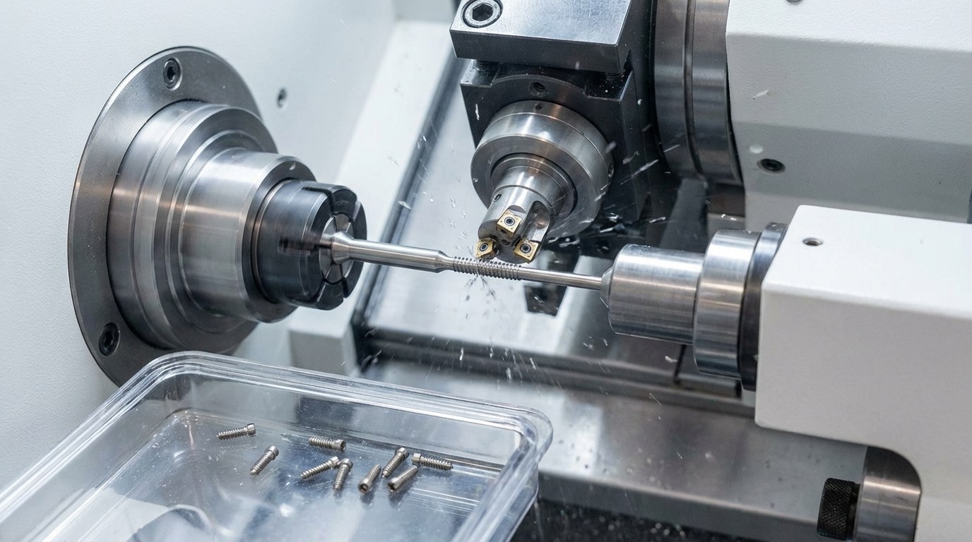
Step 6: External Thread Whirling (Core Process)
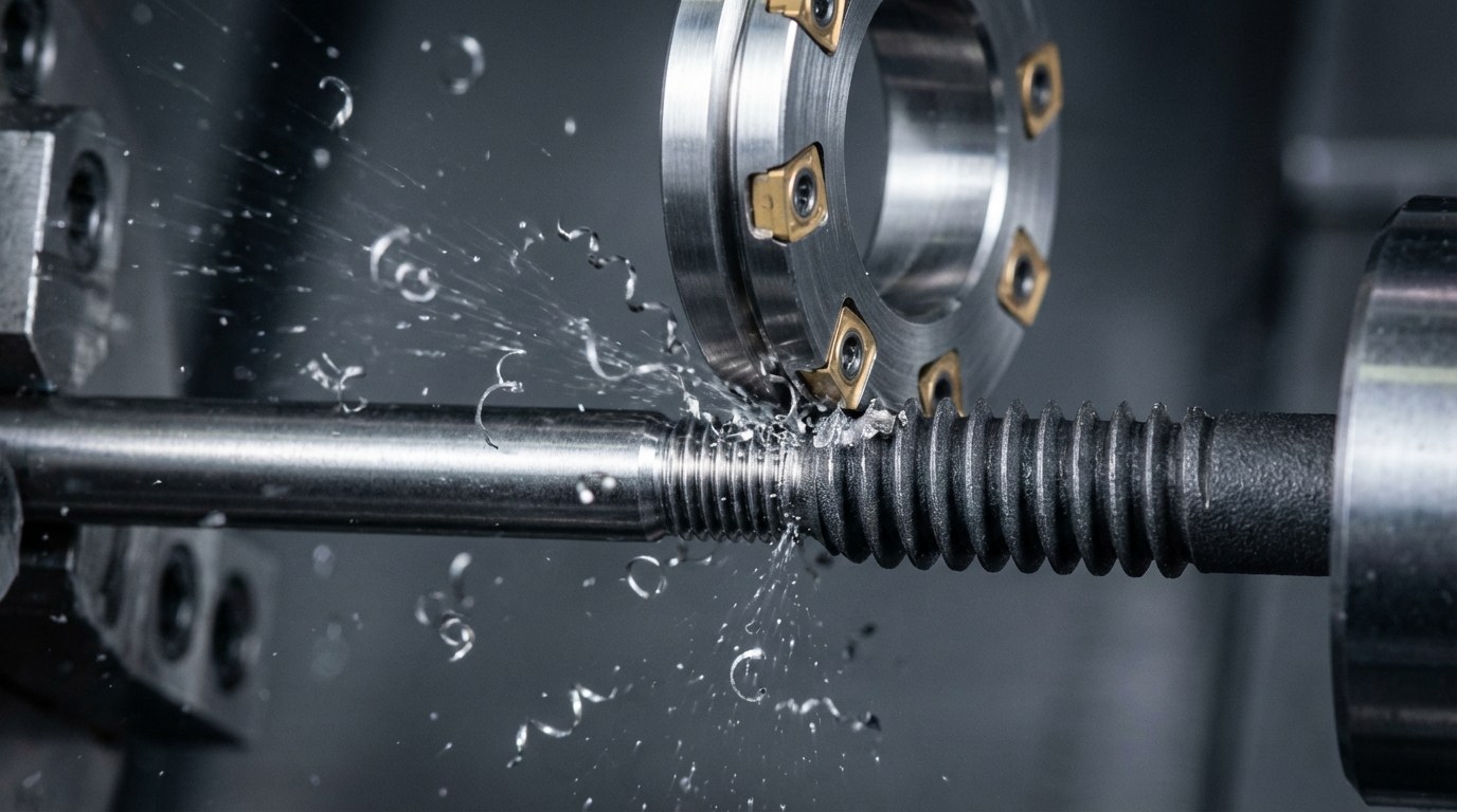
The micro whirling attachment performs single-pass forming of the external osseointegration thread.
- Attachment speed: 5,000-7,000 rpm (smaller diameter requires higher speed)
- Spindle speed (C-axis): 20-35 rpm
- Feed rate: 0.08-0.15 mm/r
- Depth of cut: Single-pass forming
- Variable pitch: Achieved through C-axis speed variation; continuous transition from dense neck pitch to sparse apical pitch
- Cooling: 120bar high-pressure oil-based cutting fluid, internal + external dual flushing
- Inserts: 4-6 uncoated ultra-fine grain carbide custom inserts
Due to small implant diameter (φ3-5mm), the whirling cutter head is also correspondingly small (φ15-25mm), with reduced insert count (4-6), but lower individual insert cutting load, more favorable for surface finish improvement.
Step 7: Surface Finishing
Medical implant-grade deburring. Miniature chamfering tools remove thread start/end sharp edges, followed by ultrasonic cleaning (5-step cleaning: solvent wash → DI water rinse → acid passivation → DI water rinse → ethanol dehydration). Final surface must show no visible burrs, chip residue, or contamination traces.
Step 8: Full Inspection
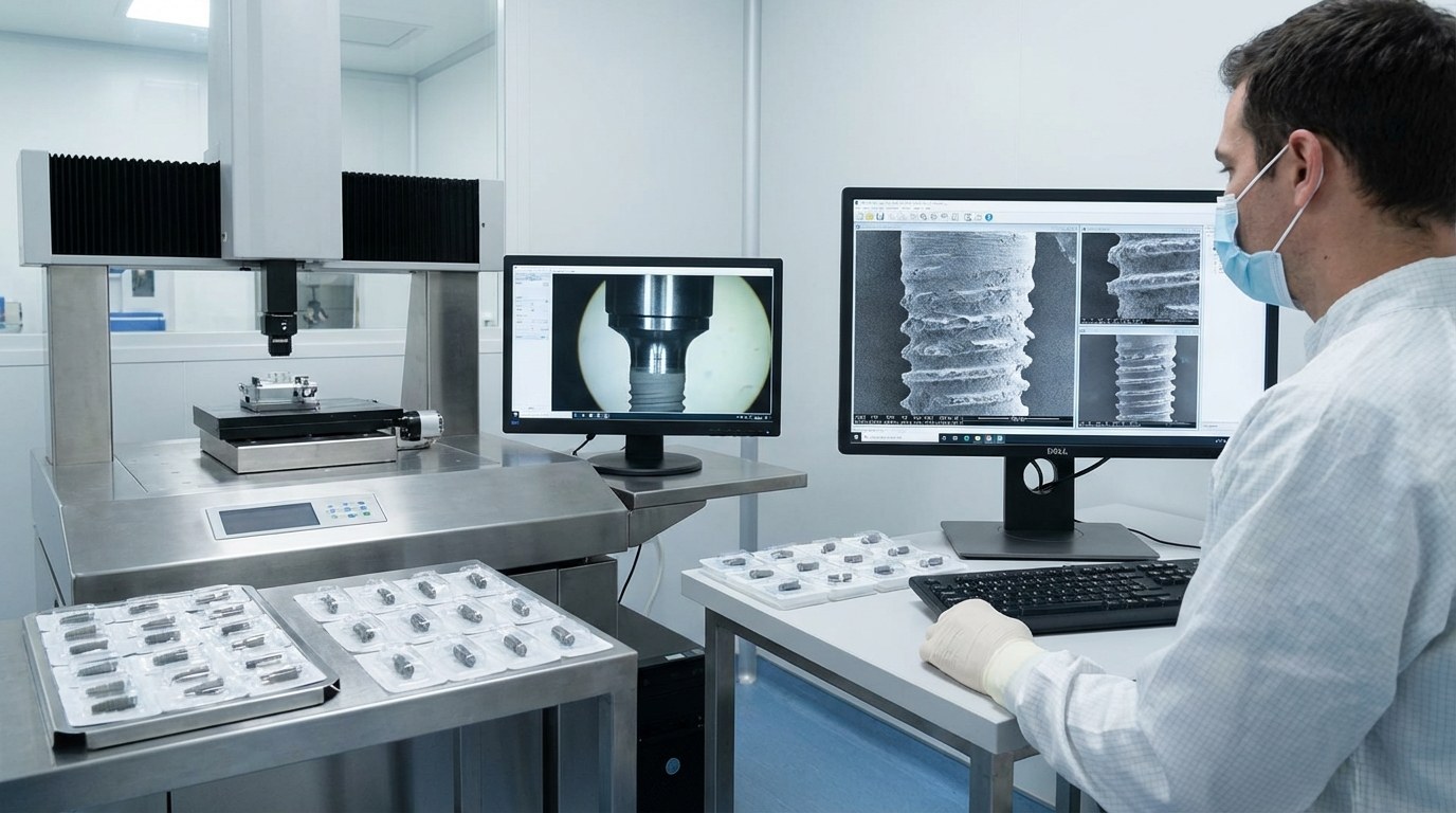
Dental implants undergo 100% full inspection covering:
- External thread pitch diameter: CMM measurement, tolerance per 4H class
- Internal thread GO/NO-GO: Thread plug gauge 100% inspection
- Internal/external thread coaxiality: CMM measurement, ≤0.01mm
- Variable pitch accuracy: Tooth-by-tooth pitch measurement, continuous transition without jumps
- Surface roughness: External thread Ra0.4-1.6, internal thread Ra0.4-0.8
- Platform perpendicularity: ≤0.005mm
- Visual: No cracks, burrs, or folds under 20x microscopy
Machining Challenges and Solutions
Challenge 1: High Coaxiality Requirements for Dual Internal/External Threads
Implant external thread (osseointegration) and internal thread (abutment connection) coaxiality must be ≤0.01mm. Traditional processes require two separate clampings for internal and external threads, with clamping eccentricity error typically 0.03-0.05mm, difficult to meet requirements. The whirling solution completes all machining in a single clamping: internal thread milling → platform turning → external thread whirling, without releasing the workpiece. The Swiss-type lathe guide bushing provides absolute positioning reference, with coaxiality guaranteed by machine accuracy (positioning accuracy ±0.002mm).
Challenge 2: Continuous Transition Accuracy for Variable Pitch
Dental implant variable pitch typically transitions from 0.6-0.8mm at the neck to 1.0-1.2mm at the apex, requiring completely continuous transition without pitch discontinuity points. Traditional turning discretizes the gradient into multiple constant-pitch segments, inevitably creating micro-jumps between segments. The whirling solution achieves completely continuous pitch gradient through macro program control of continuous C-axis speed variation (typically using quadratic curve or cubic spline interpolation), with pitch transition smooth without any step changes. Laser interferometer measurement confirms pitch transition error within ±0.003mm.
Manufacturing Case Study
Customer Background
A well-known domestic dental implant manufacturer with three product lines covering standard implants, tapered implants, and immediate loading implants, targeting 1 million-piece annual capacity. Original production line used imported 5-axis machining centers with thread milling.
Technical Challenges
- Internal/external threads machined separately, coaxiality exceeding specifications causing 3-5% customer complaint rate
- Variable pitch implant pitch transition section pass rate only 85%
- Thread milling cycle time of 4-6 minutes per piece, capacity unable to meet market growth demand
Solution
| Improvement Item | Before | After |
|---|---|---|
| External Thread Process | 5-axis center thread milling | Swiss-type lathe + micro whirling |
| Internal/External Coaxiality | Two clampings, separate machining | Single clamping, sequential completion |
| Variable Pitch Machining | Discrete multi-segment constant-pitch milling | C-axis variable speed continuous gradient whirling |
| Cooling Method | Standard external flood coolant | 120bar high-pressure internal coolant |
Implementation Results
- 100% coaxiality pass rate: Internal/external thread coaxiality improved from 0.03-0.05mm to ≤0.01mm; customer complaint rate dropped to zero
- 99.5% variable pitch pass rate: Smooth pitch transition, pass rate improved from 85% to 99.5%
- 8x capacity increase: Cycle time reduced from 5 minutes to 35 seconds, annual capacity increased from 300,000 to 2,400,000 pieces with same equipment count
- 70% tooling cost reduction: Monthly insert consumption reduced from 30,000 to 9,000 RMB
Customer Feedback
“The most surprising improvement from whirling was the internal/external thread coaxiality. Previously using 5-axis centers to mill threads separately, coaxiality fluctuated around 0.03mm, with occasional customer complaints about stiff abutment engagement. After switching to single-clamping Swiss-type lathe, coaxiality stabilized below 0.01mm — this problem disappeared completely.”
Common Questions
Q1: Can whirlwind-milled implant surfaces proceed directly to SLA sandblasted-acid-etched treatment?
Yes. The low-temperature characteristic of whirling interrupted cutting prevents α-case oxide layer formation on the TC4 ELI surface, with post-machining surface roughness of Ra0.4-0.8, allowing direct entry into SLA treatment. Conventional turning produces an oxide layer at high temperatures that must be removed by hydrofluoric acid pickling first, adding process steps and making pickling depth difficult to control precisely, leading to inconsistent surface roughness.
Q2: Different implant brands have significantly different thread profiles — how does whirling adapt?
Whirlwind milling adapts to different thread profiles through customized inserts. Whether V-type, square-type, saw-type, or hybrid profiles, simply order inserts with the corresponding contour. Custom insert lead time is typically 3-5 days, costing approximately ¥500-800 per set. One insert set can machine 600-1,000 pieces, with per-piece insert cost of only ¥0.5-1.
Q3: What are the yield rate and capacity data for implant whirling?
Taking a φ4.0×11mm standard implant as an example, single-piece cycle time is 35 seconds (including loading/unloading), with one-shift (8-hour) capacity of approximately 750 pieces. Overall yield rate exceeds 99% (including rework returns), with thread process yield rate of 99.8%. Primary defects are minor surface scratches rather than thread precision out-of-tolerance.
Q4: What are the differences between TC4 ELI and standard TC4 in whirling?
TC4 ELI (Extra Low Interstitial) has oxygen content ≤0.13% (standard TC4 ≤0.20%) and iron content ≤0.25% (standard TC4 ≤0.30%). Lower impurity content provides better ductility but slightly increased tool adhesion tendency during cutting. For whirling parameters, ELI grade attachment speed can be increased 5-10% to leverage its better ductility, while coolant lubricity must be enhanced to suppress tool adhesion. Insert selection is the same for both — uncoated ultra-fine grain carbide is recommended.
Q5: Can the machining sequence of implant internal thread milling and external thread whirling be reversed?
Internal first, external second is recommended. Two reasons: first, although whirling cutting forces are small, there is still a radial component — if external threads are machined first, they may undergo slight deformation from internal hole cutting forces. Second, internal hole machining generates chips that could scratch already-machined external threads if the internal process comes last. The internal-first, external-second sequence maximizes product quality.
Q6: Can whirling meet FDA and NMPA registration requirements for implants?
Absolutely. Whirlwind-milled implants achieve or exceed international standard requirements in thread precision (4H grade), internal/external coaxiality (≤0.01mm), surface roughness (Ra0.4-0.8), and surface integrity. In ISO 14801 fatigue testing, whirlwind-milled implants typically show 20-30% longer fatigue life than turned parts, because the more uniform residual compressive stress distribution from whirling benefits fatigue performance.
Summary
Dental implants are among the implantable devices with the highest thread machining precision and surface quality requirements. The high coaxiality demands of dual internal/external threads, continuous transition accuracy of gradual variable pitch, and the difficult-to-machine characteristics of TC4 ELI material create bottlenecks in both efficiency and quality for conventional turning and thread milling. Micro external thread whirling, with its low-temperature interrupted cutting eliminating surface oxide layers, single-clamping guaranteeing internal/external thread coaxiality, and C-axis linkage enabling continuous variable pitch, has become the preferred process for dental implant thread machining. For implant manufacturers with annual capacity exceeding 500,000 pieces, the Swiss-type lathe + micro whirling solution typically achieves ROI within 8-12 months.
If you are facing dental implant thread machining challenges (such as internal/external coaxiality, variable pitch accuracy, or surface quality), or looking to improve production efficiency and reduce costs, contact us for customized solutions.